Proposed Factory
Warning: Array to string conversion in /var/www/wp-includes/formatting.php on line 1096
HomeWECU Factory
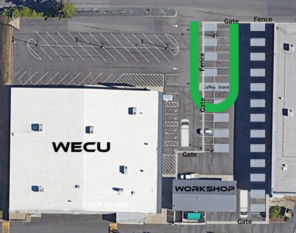
Available factory and site with proposed overlay
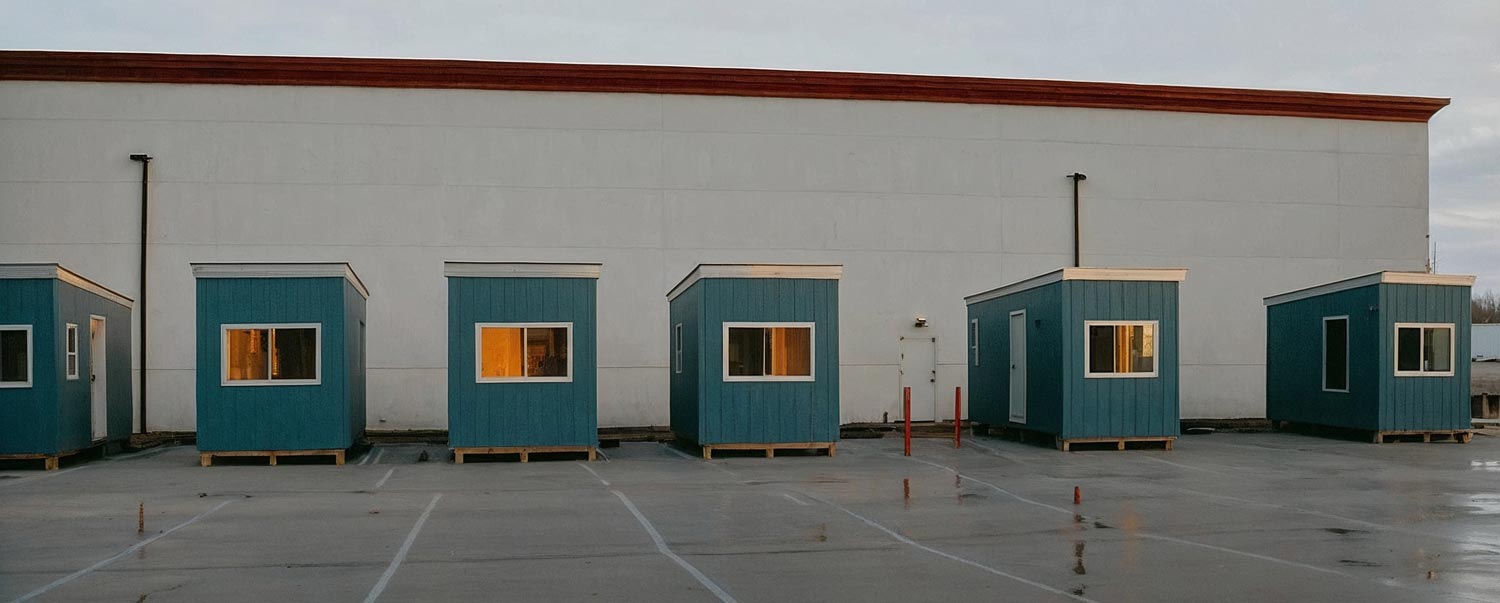
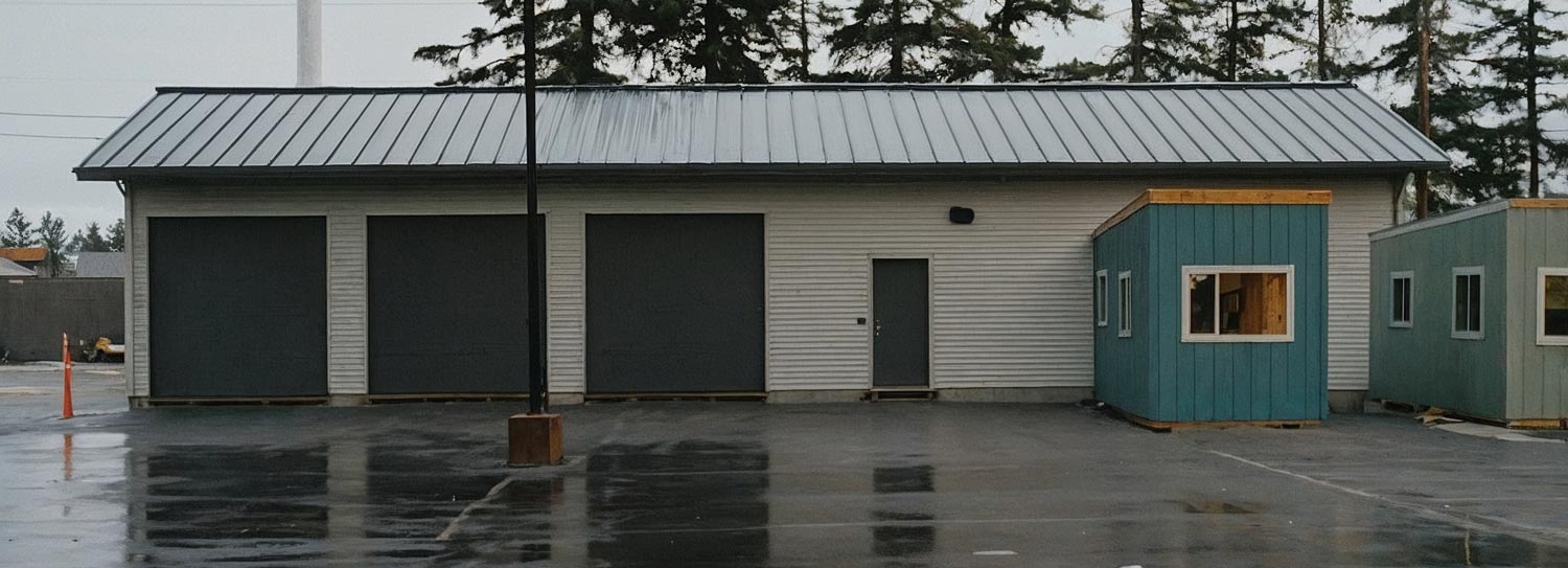
Current Modular/Scalable Structures
Condi-Optimum
Single 15’X8’X10′ unit
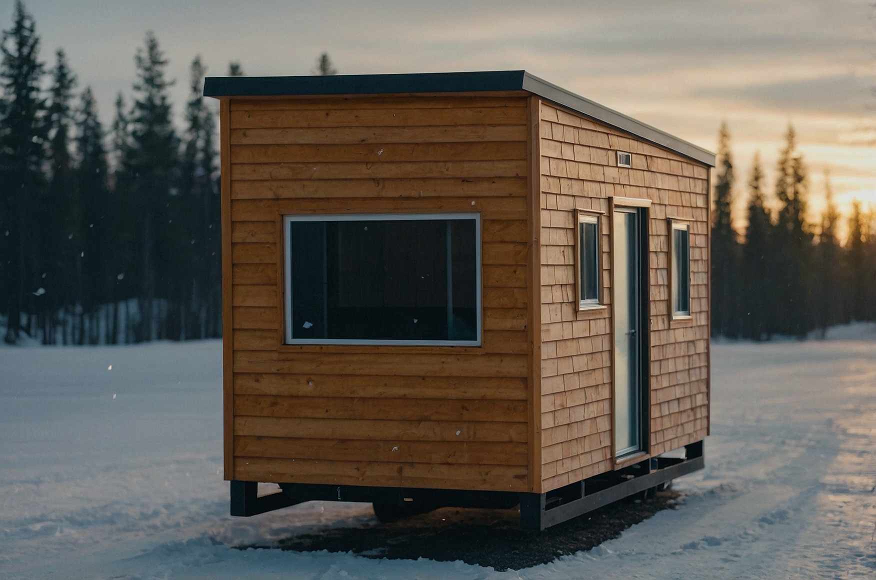
Standard setup
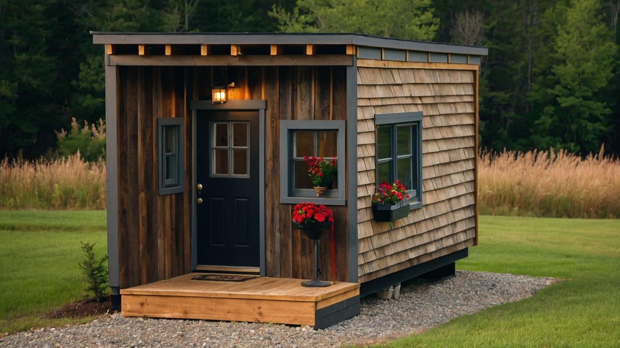
CondiMinimum
Single 14’X8’X10’/Porch
Factory Production
Lumber Preparation:
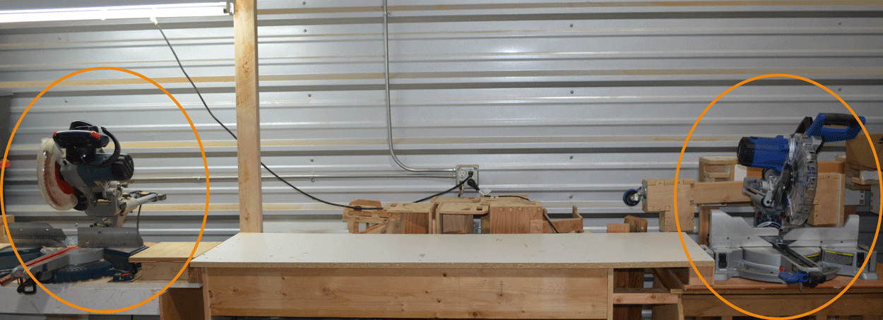
Begin with cutting the lumber bundles for the Frames and Floors using two miter saws.
The first saw is set at a 5-degree bevel for roof slope cuts, and the second saw is set at 90 degrees for all other cuts.
This setup ensures accuracy and saves time by eliminating the need to adjust the saw’s bevel angle repeatedly.
Frame and Floor Assembly with Jigs:
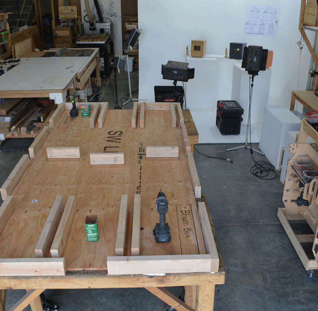
Use wall and floor jigs that are constructed to the height of the structure and no more than 48″ wide.
The jigs have predetermined stops on a 3/4″ plywood sheet, where precut and labeled 2″ x 6″ lumber is placed.
Screws and screw drills, instead of nail guns, are used to join the joints for safety and ease of correcting mistakes.
This arrangement eliminates the need for on-site lumber measurement and cutting, enhancing efficiency and simplifying training for workers.
3.Sheathing Preparation:
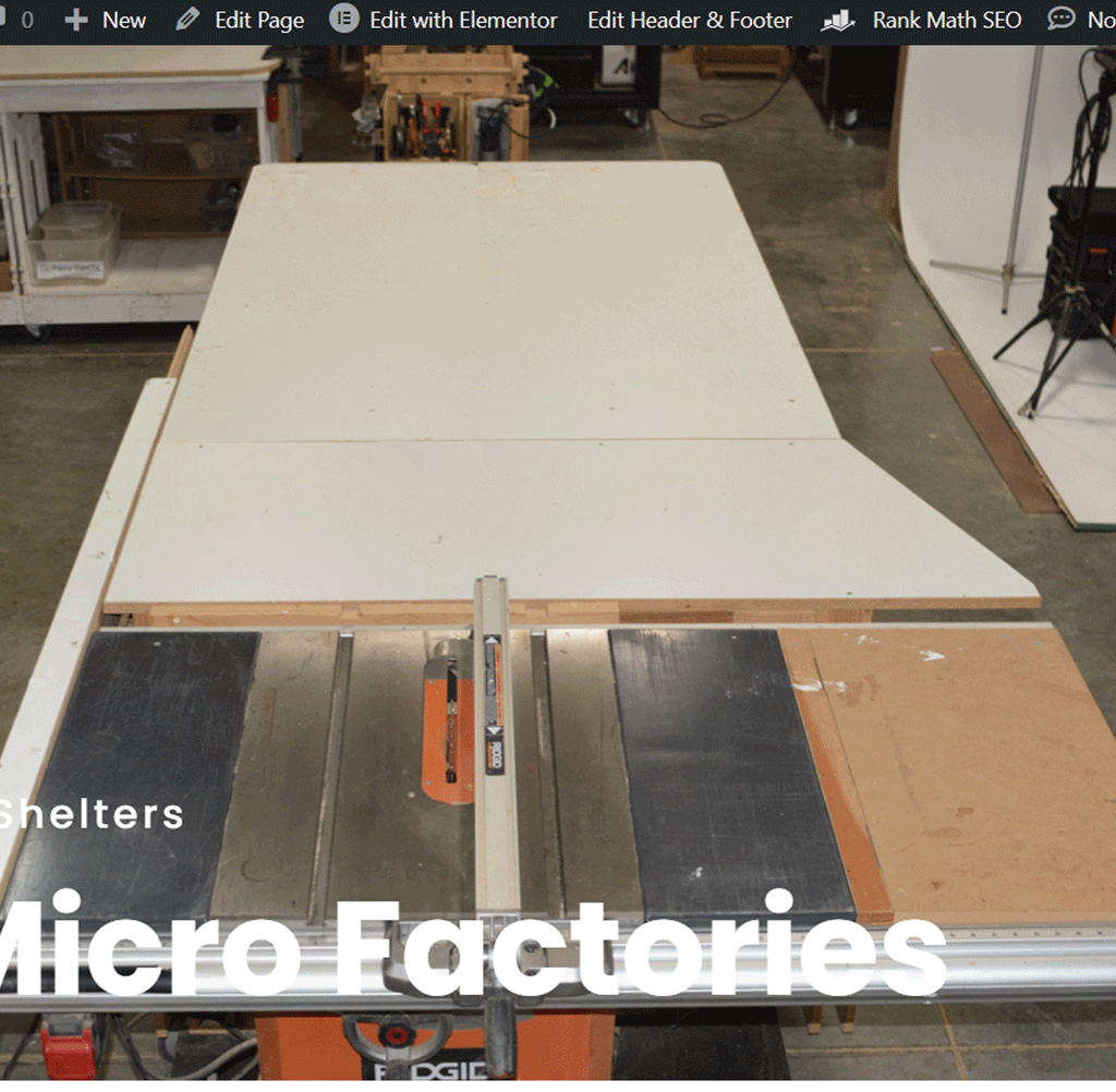
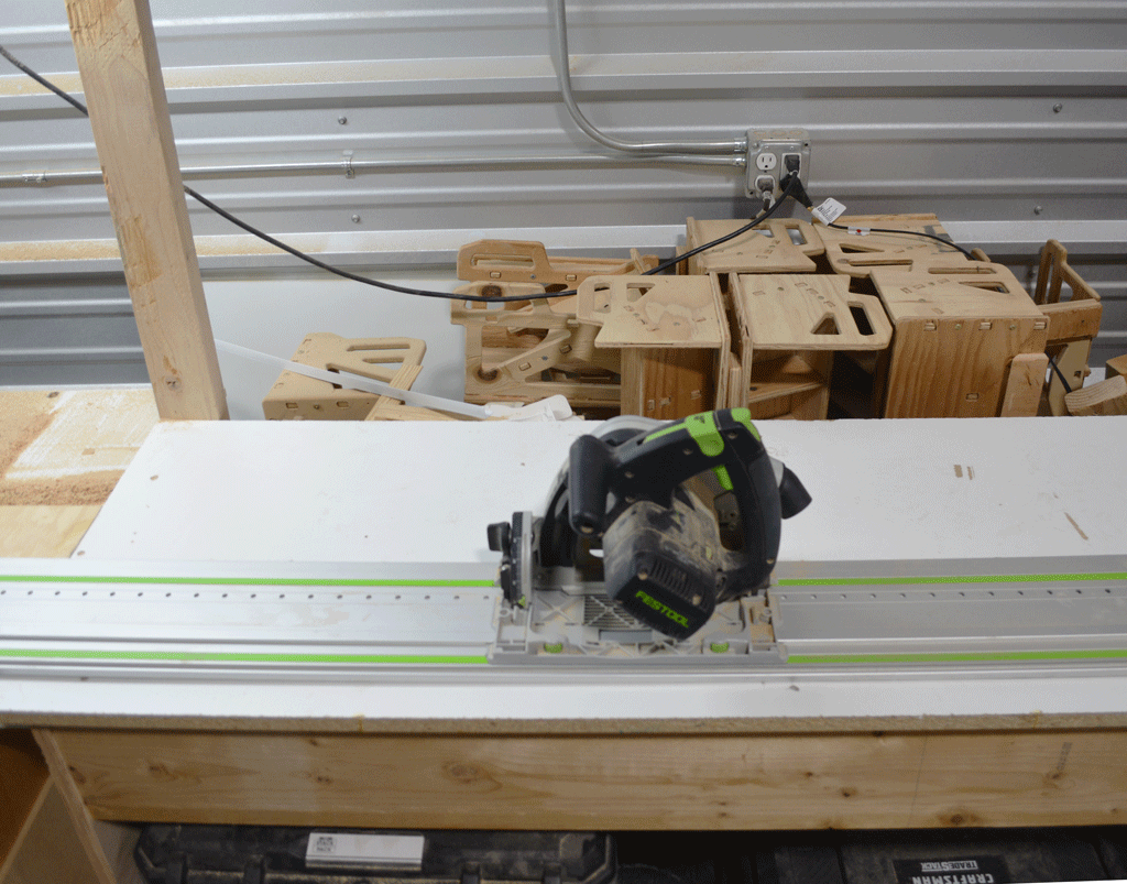
Cut the width of the sheathing on a table saw.
Use a track saw along with a template for precise length and angle cuts.
Each sheathing panel comes with a custom template, which aligns with its corresponding frame section, to mark attachment points.
Pre-marked points ensure accurate and efficient attachment, eliminating the need for onsite measuring and mitigating errors.
Assembly and Packing:
Once the sheathing is cut and marked, it is assembled into a sheathing kit.
The house kit, now containing frame and floor bundles alongside sheathing kits, is ready for either factory assembly or to be packaged on a custom pallet for flat-pack shipping.
Factory Assembly
Interior Start – Assembly Space Requirements:
The factory must have enough dedicated space for the assembly process to avoid interference with other activities.
A plan must be devised for moving the assembled structure out of the factory, and this plan needs to be tested before beginning the assembly.
Assembly Process:
The assembly will be conducted outside the factory.
Initially, the floor will be assembled inside the factory, taking advantage of the shop’s flat and level surface to ensure the base is flat and square.
Once assembled, the floor will be lifted onto a custom transport dolly and wheeled outside for the continuation of assembly.

Exterior Phase – Location and Spacing:
A designated spot in the WECU parking lot will be chosen for assembly, ensuring room for the final structure’s extraction for shipment.
A recommended clearance of at least four feet on all sides for ease of work is required.
If there is work on other structures opposite any side, the space should be doubled to eight feet to prevent interference.
Floor Placement and Leveling:
The floor will be placed on blocks to create a level build platform, ensuring a solid base for the structure.
At this stage, check to ensure the structure can be loaded onto a flatbed or flatbed trailer for removal and final site placement.
This setup will facilitate a smooth assembly process and ensure easy transportation of the completed structure.
Frame assembly
Frame Kits Selection:
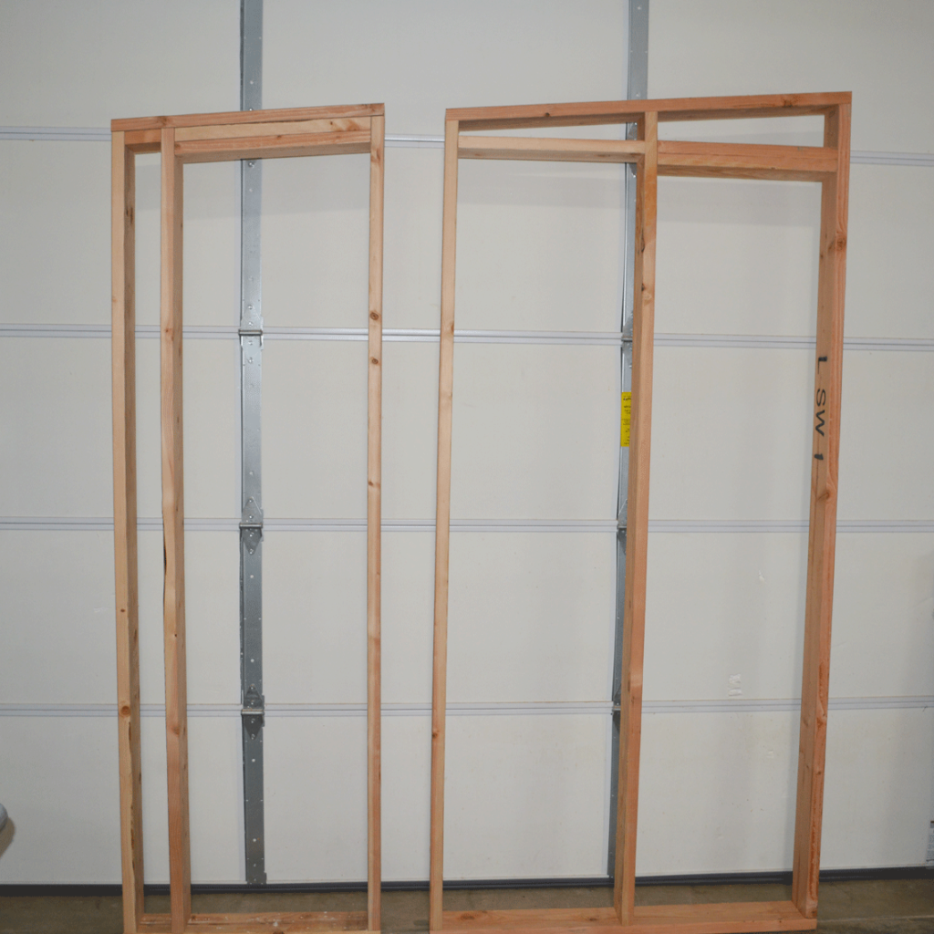
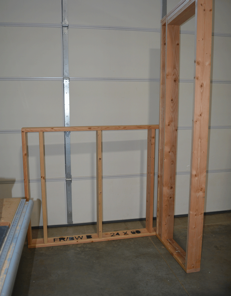
- Start with two frame kits: one for the back wall and another for the side wall without a door and minimal windows. This allows for easier initial work and helps the team develop their team-building skills.
Corner Assembly:
- Begin by joining the corner pieces of the back wall and side wall to each other and to the floor.
Use of Wooden Stops:
- The floor will have wooden stops to maintain structure quality and squareness, similar to the stops used in jigs.
- These stops will be placed and removed with spacing jigs before and after assembly.
Back Wall Completion:
- Assemble the back wall first, as it is the lightest and shortest, ensuring stability during construction.
Side Wall Completion:
- Finish the side wall assembly, and then attach the front wall’s corner piece, completing both back and front corners.
This process is designed to facilitate an organized assembly, ensuring the structure remains square and stable throughout the build.


Front Wall and Door Wall
Header Beam Attachment:
Attach header beams across the already assembled back and side walls. These beams will stabilize the sections of each wall, in conjunction with their attachment to the floor.
Front Wall and Side Wall (with Door) Assembly:
Complete the front wall assembly.
Begin the side wall with the door, starting by placing a precut spacer board at the door cutout location on the floor.
Attaching Corner Sections:
Attach the single corner sections of the side wall to the front and back walls. This may involve loosening screws on the front and back walls to adjust their alignment if necessary.
Door Section Installation:
Install the center section of the wall above the door, creating the door cutout.
Final Adjustments and Securements:
Re-secure any loose or removed screws.
Measure corner to corner to confirm the structure’s squareness.
Final Header Beam Attachment:
Attach the header beams on the front and side walls, completing the four walls to floor framing.
This sequence ensures the walls are properly aligned and stabilized, setting a strong foundation for subsequent construction steps.
Roof framing
Rafter Preparation:
Pre-cut notches at the front and back ends of the 2″ x 6″ x 15′ rafters.
Use a template to mark the drill holes.
Rafter Installation:
Position the rafters along the two side walls of the structure.
Screw the rafters to the walls from the underside.
Jig Attachment:
Attach a jig on top of each side header. These jigs are used for aligning the cross beams accurately from rafter to rafter.
Cross Beam Attachment:
Attach the cross beams between the rafters, ensuring they are properly aligned using the jigs.
This process will complete the assembly of the floor, frame, and roof, setting a solid framework for the structure.

